


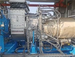

N1.0-1.6 Condensing Steam Turbine Generator Set
Dongturbo Electric Company Ltd is one of the leading manufacturers and suppliers of n1.0-1.6 condensing steam turbine generator set in China. We warmly welcome you to buy high quality customized products at competitive price from our factory. Contact us for more cheap products.
Main parameters of heat source and towed equipment
A. Heat source information | ||
1. | Heat source type | Saturated steam |
2. | Heat source temperature℃ | 202 |
3. | Heat source pressure MPa(a) | 1.6 |
4. | Heat source flow t/h | / |
B. Dragging equipment information | ||
Device Name | Generator | |
1. | Power | 1000KW |
2. | Rated Speed | 1500rpm |
3. | Voltage | 400V |
4. | Frequency | 50HZ |
Description of steam turbine body
This steam turbine is a single-casing impulse condensing gear reduction steam turbine, and it is a quick-assembly combined type, which has the characteristics of compact structure and quick installation,The steam turbine and its auxiliary equipment are divided into two large pieces: steam turbine and condenser,If conditions permit, the whole large piece will be transported to the construction site for installation.
Large steam turbine parts include: steam turbine body, drain expansion tank and chassis, etc.
The casing consists of front and rear casings, which are divided into upper and lower halves,The front casing is made of carbon steel and the rear casing is made of high-grade cast iron,The front and rear casings are connected by vertical flanges,The front casing is supported on the oil tank chassis through a front bearing seat connected by a semicircular flange,The rear casing is supported on the oil tank chassis by a rear casing bracket connected with itself,The whole casing is formed by a transverse sliding pin between the rear casing and the rear casing bracket connected with itself and a longitudinal sliding pin between the bottom of the rear casing and the oil tank chassis.
When the partition is placed in its groove, it is necessary to ensure accurate centering and free expansion,The fixing method is to place the upper and lower partitions in the casing respectively by using partners and hanging pins on the split face of the casing,A round key is connected with the casing at the bottom of the lower half of the partition,At the same time, a vertical positioning key is installed on the side face of the split face of the partition, and a gap is left at the joint to allow it to expand when heated. In order to reduce the friction loss of Peng Feng, a jacket is installed at the non-steam-filled part behind the nozzle,To reduce the axial thrust of the rotor, a balance hole is drilled in the jacket, and a straight groove is used to place it in the front casing,In order to prevent its shrinkage deformation, a "round retractor" is installed at the split face.
Seal is divided into front seal, diaphragm seal and rear seal. The front and rear steam are sealed at the front and rear ends of the casing, and the steam seal teeth are made of 0.3 mm stainless steel sheet. They are installed on the steam seal ring and the steam seal sleeve respectively, so that more steam seal teeth can be arranged in the same axial dimension, which makes the structure compact and the sealing effect good,The diaphragm steam seal adopts the structure of steel steam seal ring inlaid with copper sheet, which is pressed on the diaphragm with spring sheet.
The bearings of this unit include front bearing and rear bearing,The front bearing is the combination of thrust bearing and support bearing, which is placed in the front bearing seat and supported by a spherical bearing seat,When the rotor flexes, it can play a self-positioning role,The bearing body is equipped with adjustment pads for easy alignment and alignment.
The front bearing seat is made of high-grade cast iron,All the regulating and security components and the main oil pump are connected with each other in the front bearing seat, which is connected with the front casing by semi-circular flange, and is equipped with vertical pins and horizontal pins to keep accurate relative position after thermal expansion deformation,The front bearing seat is placed on the oil tank chassis, and its connecting screws have enough clearance so that the bearing seat can slide along the chassis.
Flow passage
The flow passage consists of one regulating stage and seven pressure stages.
In order to reduce the steam leakage loss of the stage, axial steam seals are adopted between the stator and rotor blades of the speed stage.
In order to reduce friction loss, a 50% shield is also installed at some pressure stages with steam admission degree less than 50% (the regulating stage is partial steam admission (upper half), and the part without steam admission is covered by passport (lower half), which can reduce friction blast loss caused by partial steam admission and improve efficiency).
The rotor adopts a thin impeller sleeve structure, which is separated by a steam seal sleeve in the middle,When the rotor is sleeved, the steam seal sleeve can be used to align the gap between the moving and static blades,The impeller is installed on the shaft in red and is equipped with an axial key to prevent the impeller from rotating when it is loose.
The impeller is forged from medium carbon chrome molybdenum steel, the moving and static blades are milled from chrome stainless steel, and the blades are installed into the impeller with T-shaped or hooked T-shaped blade roots.
The steam seal sleeve is sleeved on the main shaft with a red sleeve and fixed with a tight roll,The thrust disc and the axial displacement baffle are installed on the shaft with a certain interference.
Regulation, oil circuit, security system
Regulating system
Function of the regulating system of this unit: when the unit runs alone and the load changes, the speed of steam turbine can be automatically maintained within a certain range; When the unit runs in parallel power grid and the external load changes, it can meet the demand of load distribution.
When the unit speed is rated speed (6500 rpm), the main oil pump inlet pressure is 0.07MPa (meter), the outlet oil pressure is 0.67MPa (meter), and the pulse oil circuit oil pressure is 0.37MPa (meter)
The rate of speed difference δ = 4.5 0.5%, and the slow rate ε ≤ 0.5%.
The speed change range of synchronizer at no load is-4 ~+6% of rated speed, which can be-6 ~+6% according to special requirements of users.
The regulating system is composed of main oil pump, pressure converter, wrong throttle and oil motor.
As a regulating pulse signal, the speed change of the steam turbine changes the oil pressure at the outlet of the oil pump, which causes direct pulse, moves the slide valve of the pressure converter, changes the oil pressure of the pulse oil circuit, and is the superposition of amplified pulses.
Oil circuit system
The regulating oil and lubricating oil of the unit are supplied by the same radial drilling centrifugal main oil pump,When the unit runs at rated speed, the oil output pressure of the main oil pump is 0.67MPa (meter), and the high pressure oil is divided into four paths: one path leads to the lower part of the pressure converter, and one path branches off to the pulse oil path after passing through the orifice; All the way through the wrong throttle to the oil motive; All the way through the security system to the main valve; All the way to the oiler, supplying injection pressure oil.
The oil pressure at the outlet of the oiler is 0.15MPa (meter), and the low pressure oil is divided into three paths: one path is cooled by the oil cooler for lubrication of each bearing; All the way to the main oil pump, so that the main oil pump inlet causes positive pressure, ensuring the reliability of the main oil pump; All the way is connected with the low-pressure oil circuit of the governor to reduce the fluctuation of the governor caused by external interference.
At the rated speed of the unit, the pressure increase of the main oil pump is 0.6MPa, and when the working flow rate is 500L/min, the oil pressure waviness is less than 0.05 kg/cm2/(liter/second).
Security system
(1) Emergency interrupter: it is a protection device to prevent the rotor from exceeding the allowable speed, and is installed on the extension shaft connected with the main shaft,The emergency interrupter used in this unit is centrifugal flying hammer type, and an eccentric heavy hammer is installed in the radial direction of the extension shaft, which is balanced by a spring force at normal speed,When the speed exceeds 11-11.2% (i.e., the speed is 7150 ~ 7280 r/min),
(2) Critical breaking throttle: The mechanism for controlling the quick closing of main valve and regulating valve by manual or accepting the action of critical breaking device is installed on the right side of front bearing seat, that is, on one side of driver's operation channel,When the critical breaking device acts, the retractor is broken off, and the slide valve moves upward under the action of spring tension to cut off the high-pressure oil path leading to magnetic breaking throttle,At the same time, the oil of main valve casing is discharged to the oil tank from the oil drain hole, so that the main valve and regulating valve can be quickly closed.
When emergency stop is needed, pat the small spring cover by hand to release the retractor, and repeat the above actions to close the main valve and speed regulating valve quickly; To restore the oil circuit that opened the main valve, it is only necessary to press down the large spring cover and re-hang the retractor.
(3) Axial displacement interrupter: it is a safety device to prevent the relative displacement of steam turbine rotor in the axial direction from exceeding the allowable value.
When the relative displacement of the rotor exceeds 0.7mm, the clearance between the oil nozzle and the baffle plate increases, and the throttle oil pressure in the axial position controller decreases to 0.25MPa (meter),The slide valve moves upward under the action of spring force, opening the oil drain window, cutting off the high-pressure oil circuit of the quick-closing combination device, and quickly closing the main valve and regulating valve. In case of emergency stop, pull the handle, cut off the high-pressure oil circuit, and close the main valve and regulating valve quickly. After the accident is eliminated, the slide valve must be pushed down by hand to restore its original position.
(4) Magnetic cut-off throttle: In case of emergency, the operator can manually push the button to turn on the power supply, so that the magnetic cut-off throttle can operate and stop urgently,The shutdown principle is the same as 2 and 3 .
(5) When the high-pressure oil pressure is reduced to ~0.55MPa (meter), the electric oil pump is started and put into operation to ensure the lubrication of various parts of the bearing,When the lubricating oil pressure is reduced to 0.055MPa (meter), a shutdown signal is sent by turning on the power supply through the pressure switch.
(6) All bearings adopt resistance remote thermometer,When the temperature of bearing oil return rises to 65℃, the circuit is connected and an alarm signal is sent out.
(7) The front side of the fuel tank is provided with an oil level gauge, so that drivers can easily monitor the oil level of the fuel tank.
Condenser system
The condensing system of this unit includes: condenser, condensate pump, vacuum pump, exhaust nozzle, safety diaphragm and other components. The main function of the condensing system is to ensure that the unit operates under the designed vacuum. In order to ensure the vacuum in the exhaust device, the unit is equipped with a vacuum pump to pump out the air leaked into the condenser. The vacuum pump rapidly increases the vacuum of the condenser when starting, and the pumped gas-water mixture is discharged into the trench together.
The top of the condenser is equipped with a safety membrane plate,When the pressure of the condenser rises to 0.103~0.106 MPa(absolute) due to the decrease of vacuum, the safety membrane plate will automatically open, and exhaust the spent steam to the atmosphere to protect the condenser from damage.
The exhaust pressure of steam turbine is 10kPa(A), and the exhaust steam enters the condenser to condense into water.
Turning gear
Provide a complete set of electric turning gear, which is integrated on the reduction box; The device can also be manually turned on the spot, and the turning can start the rotor from the static state and run continuously under the normal bearing lubricating oil pressure, and the turning speed is 5 ~ 10 rpm.
The device is of manual meshing type, and turning gear can be put into operation only when the shutdown speed reaches zero, so that the steam turbine generator can be turned from a static state, and the steam turbine rotor can be cooled uniformly to avoid thermal bending.
The turning gear is driven by AC motor, and the turning system is equipped with pressure switch and lubricating oil pressure interlock protection device. In case of oil supply interruption or oil pressure reduction to unsafe value during the operation of turning gear, it should give an alarm in time and stop running.
Once the steam turbine starts up to a certain speed, the barring will automatically exit without impacting the steam turbine and re-engaging.
Monitoring, protection and control system of steam turbine
Turbine Supervisory Instrumentation system(TSI)
(1) TSI selects Wuxi Houde products.
(2) The items of steam turbine body detection instruments at least include: 1 point of axial displacement, 2 points of bearing seat vibration and 3 points of steam turbine speed. The output signal of the device is 4~20mADC(2 pairs), and the signal acting on ETS also outputs the switch signal.
Emergency Trip System (ETS)
(1) The turbine shall be designed with mature and reliable overspeed protection device, and Party B shall provide overspeed action value.
(2) Emergency stop button is set in the main control room to achieve the purpose of safe operation; In case of failure of DCS system, the emergency stop button can ensure the safe stop of equipment, and the emergency stop system of steam turbine is required to meet this requirement.
(3) At least has the following shutdown protection items (ETS):
Overspeed protection (two out of three)
Large axial displacement protection
Bearing seat vibration protection
Lubricating oil low pressure protection
Vacuum low protection
High bearing temperature interlock shutdown
Others
Main parameters of generator
Model | 1FC6 5606-4LA42 | ||
Parameters | Capacity: 1000KW | Structure: IMB 20 | |
Voltage: 400V
| Rotation (viewed from the drive end of the generator): clockwise | ||
Current: 1804A | Connection: three-phase four-wire system | ||
Frequency:50HZ | Center height: see generator dimentional drawing | ||
Speed: 1500r/min | Operating conditions: parallel connection, long-term continuous operation | ||
COSф 0.8 lag | Bearing type: sliding (forced lubrication) | ||
Insulation grade: Class F. | Anti-interference level: VDE standard N level | ||
Protection grade: IP23 | Ambient temperature and specifications: VDE 40℃ | ||
Voltage regulation mode: phase compound excitation | Application occasion: land use | ||
Load situation: normal load | Efficiency:≥93.8% | ||
Temperature rise grade: F | |||
Connection of stator coil: Y | |||
Voltage regulation mode: phase compound excitation | Ambient temperature and specifications: VDE 40℃ | ||
Terminal box | Outlet direction: right side (seen from the driving end of generator) | ||
Air-water cooler: none | Air filter: Yes | ||
Anti-condensation heater: Yes | Winding temperature detection: two sets of temperature sensors PT100 (one set for standby) | ||
Face-coating/painting: Determine within one month after signing the technical agreement | |||
List of Main Supply Equipment (Single Unit)
No. | Parts | Qty. | Re-marks |
1 | Steam Turbine Body | 1 set | From the inlet reverse flange to the exhaust reverse flange |
2 | Gear box | 1 set | Power: 1000kW Rotating speed: 6500/1500rpm |
3 | Condenser | 1 set | |
4 | Condensate Pump | 2 sets | |
5 | Water Ring Vacuum Pump | 2 sets | |
6 | Water Filter | 1 set | |
7 | DC Oil Pump | 1 set | |
8 | Centrifugal Electric Oil Pump | 1 set | YCB0-0.6 |
9 | Generator (including excitation system) | 1 set | Power: 1000kW Voltage: 400kV Rotating speed: 1500rpm Frequency: 50HZ |
10 | Regulatory system | 1 set | Full hydraulic adjustment |
11 | Steam turbine control cabinet | 1 set | |
13 | Auxiliary cabinet of steam turbine | 1 set | |
13 | Steam turbine local cubicles | 1 set | |
14 | Generator control cabinet | 1 set |
Special tools and accessories for steam turbine
No | Parts | Qty. | Remarks |
1 | Turning tool bar | 1 | |
2 | Casing loading and unloading wrench | 2 | |
3 | inner hexagon spanner | 1 set | |
4 | Wrench for emergency breaker | 1 | |
5 | guide post | 2 | |
6 | Inclined shim | 88 | |
7 | Tool for removing bearing bush | 1 | |
8 | Tool for lifting casing and rotor | 1 | |
9 | foundation bolt | 22 | Used for steam turbine and condenser |
Spare parts of steam turbine
No. | Parts | Unit | Qty. | Re-marks |
1 | Gland piece 228.4 | pce | 20 | Steam seal for shaft |
2 | steel wire | pce | 40 | Steam seal for shaft |
3 | Gland piece 184.4 | pce | 20 | Steam seal for shaft |
4 | leaf spring | pce | 8 | L=109 |
5 | leaf spring | pce | 8 | L=104 |
6 | leaf spring | pce | 8 | L=117 |
7 | The first stage diaphragm gland | pce | 1 | diaphragm gland |
8 | Secondary and tertiary diaphragm steam seals | pce | 2 | diaphragm gland |
9 | The 4th ~ 6th diaphragm gland | pce | 3 | diaphragm gland |
10 | 7 ~ 8 diaphragm gland | piece | 2 | diaphragm gland |
11 | spring | piece | 1 | Emergency interrupter |
12 | Oil seal ring | piece | 2 | Main oil pump |
Electrical Instruments of Steam Turbine
No. | Parts | Model | Unit | Qty. | Re-marks |
1 | Pressure Transmitter | FD80BCFIIIERM2 | pce | 1 | Inlet steam pressure |
2 | Pressure Transmitter | FD80BCFIIIERM2 | pce | 1 | Condenser vacuum |
3 | Pressure Transmitter | FD80BCIIIERM2 | pce | 1 | Lubricating oil pressure |
4 | Pressure Gage | Y-100 | pce | 2 | Vacuum pump extraction pressure |
5 | Pressure Gage | Y-100 | pce | 1 | Cooling water inlet pressure |
6 | Pressure Gage | Y-100 | pce | 1 | Outlet pressure of cooling water |
7 | Pressure Gage | Y-100 | pce | 1 | Inlet water pressure of oil cooler |
8 | Pressure Gage | Y-100 | pce | 1 | Outlet water pressure of oil cooler |
9 | Pressure Gage | Y-100 | pce | 1 | Main valve inlet pressure |
10 | Seismic Pressure Gauge | Y-100 | pce | 1 | Outlet pressure of 1# condensate pump |
11 | Seismic Pressure Gauge | Y-100 | pce | 1 | Outlet pressure of 2# condensate pump |
12 | Resistor Remote Transmission PT100 | pce | 1 | Thrust shoe temperature | |
13 | Resistor Remote Transmission PT100 | pce | 1 | Temperature of front bearing bush | |
14 | Resistor Remote Transmission PT100 | pce | 1 | Temperature of rear bearing bush | |
15 | Resistor Remote Transmission PT100 | WTYY-1021 | pce | 1 | Lubricating oil supply temperature |
16 | Resistor Remote Transmission PT100 | WTYY-1021 | pce | 1 | Tank temperature |
17 | Bimetal Thermometer | WSS-411 | pce | 1 | Inlet oil temperature of oil cooler |
18 | Bimetal Thermometer | WSS-411 | pce | 1 | Condenser inlet water temperature |
19 | Bimetal Thermometer | WSS-411 | pce | 1 | Outlet water temperature of condenser |
20 | Bimetal Thermometer | WSS-411 | pce | 1 | Condenser outlet oil temperature |
21 | Bimetal Thermometer | WSS-411 | pce | 1 | Hot well temperature |
22 | Armoured Thermal Resistance Matching Pipe | WZPK-231 | pce | 1 | Inlet steam temperature |
23 | Armoured Thermal Resistance Matching Pipe | WZPK-231 | pce | 1 | Exhaust temperature |
24 | Magnetoresistive Speed Sensor | SZCB-01 | pce | 3 | Rotating speed (Wuxi Houde) |
25 | Vibration Speed Sensor | ST-A3-B(HD-ST-3) | set | 2 | Bearing Vibration (Wuxi Houde) |
26 | Eddy Current Sensor | WT-¢8 | set | 1 | Axial displacement (Wuxi Houde) |
27 | Magnetic Level Gauge | UHZ-661-A1A2A-80 0A-F3 | set | 1 | Hot well level |
28 | Liquid Level Transmitter | FD80BAIIIERM2d | set | 1 | Tank level |
29 | Electric Heater | SRY4 AC220V/2KW | pce | 3 | Tank heater |
30 | Pressure Switch | pce | 3 |
List of Main Subcontractors
No. | Item | Supplier |
1 | Gear Box | Nanjing Chuangli |
2 | Gear Pump | Hebei Hengsheng |
3 | Condenser | Shandong Sante |
4 | Condensate Pump | Zhejiang Water Pump General Factory |
5 | Water Ring Vacuum Pump | Shandong Bozhongzibo Shunhuan |
6 | Pressure Transmitter | Shandong Furuide |
7 | Pressure Gage | Zibo Dahua |
8 | Resistance Remote Transmission
| Hangzhou Minte |
9 | Bimetal Thermometer | Hangzhou Hongxing |
10 | Magnetic Level Gauge | Shanghai Sipai |
11 | Eddy Current Sensor | Wuxi Houde |
12 | Vibration Speed Sensor | Wuxi Houde |
13 | Magnetoresistive Speed Sensor | Wuxi Houde |
14 | Pressure Switch | Changzhou Tianli |
15 | Generator | CSIC Heavy Industry |
Drawings and data
The drawings and data of unit engineering design (electronic editable version and signed and sealed version, provided within 7 days after signing the technical agreement), all drawings and technical data will use Party A's icon.
Steam turbine data sheet
Steam turbine performance curve
Steam turbine layout
Steam-water system diagram
Lubricating oil system diagram
Product use and design instructions
General assembly drawing of steam turbine, including connection drawing of steam turbine and generator,
Nozzle drawing of steam turbine
Electrical equipment installation layout, schematic diagram of control box, system diagram and wiring diagram of control box
System Manual
Instrument installation drawing, instrument material list, wiring diagram and component list;
Outline drawing, shafting drawing, electrical schematic diagram and terminal wiring diagram of generator
Data (delivered with steam turbine)
Packing list, spare parts list, random tool list, various inspection and test reports, product operation instructions, random drawings, etc.
Others
The matters not covered in this technical agreement shall be settled through friendly negotiation by all parties,If there is any change or modification, the other parties shall be notified in writing, which shall be subject to the written confirmation of all parties.
This technical agreement is an annex to the supply contract, and the effective date shall be subject to the effective date of the supply contract, and the delivery date of the drawings and materials shall be subject to the postmark date (the mailing materials shall be delivered by express mail).
Hot Tags: n1.0-1.6 condensing steam turbine generator set, China, manufacturers, suppliers, factory, customized, buy, cheap, Power Plant Components And Parts, Steam Turbine 500KW Extraction Condensing Steam Turbine For Textile Dyeing Model CN0 5 1 25 0 9, Steam Turbine Spare Parts Screws Fasteners, 150KW Micro Condensing Steam Turbine Generator Set, Manufacture fupply steam turbine blade forgings, 3MW Condensing Steam Turbine Generator
You Might Also Like


Send Inquiry