

Flow distribution characteristics in a power station oil cooler play a crucial role in ensuring the efficient and reliable operation of power generation systems. As a leading supplier of power station oil coolers, we have in - depth knowledge and extensive experience in this area. In this blog, we will explore the key flow distribution characteristics and their implications for power station oil coolers.
1. Basic Principles of Flow Distribution in Oil Coolers
In a power station oil cooler, the main function is to remove heat from the oil by transferring it to a cooling medium, usually water. The flow of oil and cooling water through the cooler is a complex process that is affected by multiple factors.
The oil enters the cooler at a certain flow rate and temperature. It then passes through a series of tubes or channels where heat exchange occurs. The cooling water, on the other hand, flows around these tubes or channels in the opposite or cross - flow direction. The distribution of flow within the cooler is not uniform, and understanding these non - uniformities is essential for optimizing the cooler's performance.
One of the fundamental concepts in flow distribution is the Reynolds number. The Reynolds number is a dimensionless quantity that describes the nature of fluid flow. In the case of an oil cooler, it helps us understand whether the flow is laminar or turbulent. Laminar flow is characterized by smooth, parallel layers of fluid, while turbulent flow is chaotic and has eddies and swirls. For most power station oil coolers, a combination of laminar and turbulent flow may exist in different parts of the cooler.
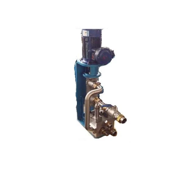

2. Factors Affecting Flow Distribution
2.1 Geometric Design of the Cooler
The physical structure of the oil cooler has a significant impact on flow distribution. The shape, size, and arrangement of tubes or channels can cause variations in flow velocity and pressure. For example, if the tubes are not evenly spaced, the oil may flow more easily through some tubes than others. This can lead to uneven heat transfer and reduced cooling efficiency.
A well - designed cooler should have a uniform cross - sectional area for the flow paths. This helps to ensure that the oil and cooling water are evenly distributed throughout the cooler. Additionally, the baffle design within the cooler can also influence flow distribution. Baffles are used to direct the flow of the cooling medium and increase the contact time between the oil and the cooling water. However, improper baffle design can cause flow stagnation or uneven flow patterns.
2.2 Inlet and Outlet Conditions
The way the oil and cooling water enter and exit the cooler also affects flow distribution. If the inlet velocity is too high, it can cause jetting and uneven flow distribution within the cooler. On the other hand, if the inlet velocity is too low, it may lead to insufficient mixing and poor heat transfer.
The location and orientation of the inlet and outlet ports are also important. For example, if the inlet and outlet ports are located in such a way that the flow has to make sharp turns, it can create flow disturbances and uneven distribution.
2.3 Viscosity of the Oil
The viscosity of the oil is a critical factor in flow distribution. As the temperature of the oil changes, its viscosity also changes. High - viscosity oil flows more slowly and is more likely to cause flow resistance. This can lead to uneven flow distribution, especially in areas where the flow paths are narrow.
In power stations, the oil may be subjected to different operating temperatures. Therefore, it is necessary to consider the viscosity - temperature relationship when designing the oil cooler. A cooler that can handle a wide range of oil viscosities is more likely to maintain a uniform flow distribution.
3. Implications of Flow Distribution on Cooler Performance
3.1 Heat Transfer Efficiency
Uniform flow distribution is essential for maximizing heat transfer efficiency. When the flow is evenly distributed, the oil and cooling water have a more consistent contact area and time for heat exchange. This results in better heat transfer rates and lower outlet oil temperatures.
In contrast, uneven flow distribution can lead to hot spots in the oil, where the heat transfer is less efficient. These hot spots can cause the oil to degrade more quickly, reducing its lifespan and potentially leading to equipment failure.
3.2 Pressure Drop
Flow distribution also affects the pressure drop across the oil cooler. A well - distributed flow will have a relatively low pressure drop, which means less energy is required to pump the oil and cooling water through the cooler.
However, if the flow is uneven, there may be areas of high flow resistance, resulting in a higher pressure drop. This can increase the energy consumption of the power station and reduce the overall efficiency of the system.
4. Monitoring and Optimization of Flow Distribution
To ensure optimal flow distribution in a power station oil cooler, it is necessary to monitor the flow characteristics. This can be done using various techniques, such as flow meters, pressure sensors, and temperature sensors.
Flow meters can measure the flow rate of the oil and cooling water at different points in the cooler. Pressure sensors can detect changes in pressure, which can indicate flow disturbances. Temperature sensors can monitor the temperature of the oil and cooling water at the inlet and outlet, as well as at different locations within the cooler.
Based on the monitoring results, adjustments can be made to optimize the flow distribution. For example, if the flow is found to be uneven, the cooler's internal structure can be modified, or the inlet and outlet conditions can be adjusted.
5. Related Equipment in Power Stations
In addition to oil coolers, there are other important equipment in power stations that are related to the overall operation of the power generation system. For example, Power Station Oil Pump is responsible for circulating the oil in the system. A well - functioning oil pump ensures a stable flow of oil to the cooler.
The Power Station Condenser is another key component. It condenses the steam back into water after it has passed through the turbine, and the cooling water used in the condenser can also be related to the cooling water used in the oil cooler.
The Power Station HP and LP Heater is used to pre - heat the feedwater before it enters the boiler. The efficient operation of these heaters can also affect the overall efficiency of the power station.
6. Conclusion and Call to Action
In conclusion, understanding the flow distribution characteristics in a power station oil cooler is essential for ensuring the efficient and reliable operation of power generation systems. As a supplier of power station oil coolers, we have the expertise and resources to provide high - quality products that optimize flow distribution and improve heat transfer efficiency.
If you are in the market for a power station oil cooler or related equipment, we invite you to contact us for more information. Our team of experts is ready to assist you in selecting the most suitable products for your power station. We can provide detailed technical support and customized solutions to meet your specific requirements.
References
- Incropera, F. P., & DeWitt, D. P. (2002). Fundamentals of heat and mass transfer. John Wiley & Sons.
- Cengel, Y. A., & Ghajar, A. J. (2015). Heat and mass transfer: A practical approach. McGraw - Hill Education.
- White, F. M. (2016). Fluid mechanics. McGraw - Hill Education.


